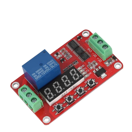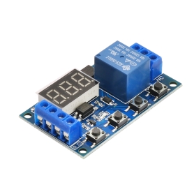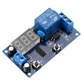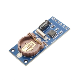
ماژول کنترل رله FRM01 یک ماژول کنترل چندکاره است که شامل 18 تابع قابل برنامه ریزی بوده که با دو تایمر جداگانه که میتوان آنها را از 0.1 ثانیه تا 270 ساعت تنظیم کرد، حلقه بینهایت یا تعداد مشخصی از دورهها و قابلیت فعال سازی رویداد با سیگنال بالا از قابلیت های این ماژول می باشد.
مشخصات
ولتاژ کاری: 12 ولت DC
جریان: 10 آمپر
ولتاژ سوئیچینگ AC: حداکثر 250 ولت
ولتاژ سوئیچینگ DC: حداکثر 30 ولت
18 تابع قابل برنامهریزی توسط کاربر
رابط 3 سیمی برای ورودی و خروجی
ابعاد: 68 میلیمتر × 42 میلیمتر
بررسی حالت های مختلف ماژول FRM01
حالت 1: وقتی برق تغذیه میشود، CH1 به حالت پایین در میآید، T1 (تایمر 1) شروع به شمارش میکند، بعد از رسیدن T1 به 0، CH1 به حالت بالا تغییر میکند.
حالت 2: وقتی برق تغذیه میشود، CH1 به حالت بالا در میآید، T1 (تایمر 1) شروع به شمارش میکند، بعد از رسیدن T1 به 0، CH1 به حالت پایین تغییر میکند.
حالت 3: وقتی برق تغذیه میشود، CH1 به حالت پایین در میآید، T1 (تایمر 1) شروع به شمارش میکند، بعد از رسیدن T1 به 0، CH1 به حالت بالا تغییر میکند. سپس T2 (تایمر 2) شروع به شمارش میکند، بعد از رسیدن T2 به 0، CH1 به حالت پایین تغییر میکند.
حالت 4: وقتی برق تغذیه میشود، CH1 به حالت بالا در میآید، T1 (تایمر 1) شروع به شمارش میکند، بعد از رسیدن T1 به 0، CH1 به حالت بالا تغییر میکند. سپس T2 (تایمر 2) شروع به شمارش میکند، بعد از رسیدن T2 به 0، CH1 به حالت بالا تغییر میکند.
حالت 5: وقتی برق تغذیه میشود، CH1 به حالت پایین در میآید، T1 (تایمر 1) شروع به شمارش میکند، بعد از رسیدن T1 به 0، CH1 به حالت پایین تغییر میکند. سپس T2 (تایمر 2) شروع به شمارش میکند، بعد از رسیدن T2 به 0، CH1 به حالت پایین تغییر میکند. این فرایند تکرار میشود.
حالت 6: وقتی برق تغذیه میشود، CH1 به حالت بالا در میآید، T1 (تایمر 1) شروع به شمارش میکند، بعد از رسیدن T1 به 0، CH1 به حالت پایین تغییر میکند. سپس T2 (تایمر 2) شروع به شمارش میکند، بعد از رسیدن T2 به 0، CH1 به حالت بالا تغییر میکند. این فرایند تکرار میشود.
حالت 7: وقتی برق تغذیه میشود، CHI1 به حالت پایین در میآید، T1 (تایمر 1) شروع به شمارش میکند، بعد از رسیدن T1 به 0، CH1 به حالت بالا تغییر میکند، T2 (تایمر 2) سپس شروع به شمارش میکند، بعد از رسیدن T2 به 0، CH1 به حالت پایین تغییر میکند. این فرایند به تعداد مشخصی بار تکرار میشود که توسط تابع NX تنظیم شده است.
حالت 8: وقتی برق تغذیه میشود، CH1 به حالت بالا در میآید، T1 (تایمر 1) شروع به شمارش میکند، بعد از رسیدن T1 به 0، CH1 به حالت پایین تغییر میکند، T2 (تایمر 2) سپس شروع به شمارش میکند، بعد از رسیدن T2 به 0، CH1 به حالت بالا تغییر میکند. این فرایند به تعداد مشخصی بار تکرار میشود که توسط تابع NX تنظیم شده است.
حالت 9: در حالی که برق تغذیه شده است، سیگنال سطح بالا میتواند ارسال شود که CH1 را به حالت بالا تغییر دهد، سیگنال سطح بالای دیگری نیز میتواند ارسال شود تا CH1 را به حالت پایین تنظیم کند.
حالت 10: در حالی که برق تغذیه شده است، سیگنال سطح بالا میتواند اعمال شود تا CH1 را به حالت بالا تنظیم کند. T1 (تایمر 1) شروع به شمارش میکند و بعد از رسیدن به صفر، CH1 به حالت پایین تنظیم میشود.
حالت 11: وقتی برق تغذیه میشود، CH1 به حالت پایین در میآید، سیگنال سطح بالا میتواند ارسال شود که باعث شمارش معکوس T1 (تایمر 1) شود و بعد از رسیدن T1 به 0، CH1 به حالت بالا تنظیم میشود، ارسال سیگنال سطح بالا در حالت CH1 بالا، CH1 را به حالت پایین تنظیم میکند و باعث شمارش معکوس T1 میشود.
حالت 12: وقتی برق تغذیه میشود، CH1 به حالت پایین در میآید، سیگنال سطح بالا CH1 را به حالت بالا تغییر داده و شمارش معکوس T1 (تایمر 1) را آغاز میکند، بعد از رسیدن T1 به 0، CH1 به حالت پایین تغییر میکند.
حالت 13: وقتی برق تغذیه میشود، CH1 به حالت پایین در میآید، T1 (تایمر 1) شروع به شمارش میکند، وقتی T1 به 0 میرسد، CH1 به حالت بالا تغییر میکند و T2 (تایمر 2) شروع به شمارش میکند. وقتی T2 به 0 میرسد، CH1 به حالت پایین میروید.
حالت 14: وقتی برق تغذیه میشود، CH1 به حالت پایین در میآید، سیگنال سطح بالا CH1 را به حالت بالا تغییر میدهد و T1 (تایمر 1) شروع به شمارش میکند، بعد از رسیدن T1 به 0، CH1 به حالت پایین میروید و T2 (تایمر 2) شروع به شمارش میکند، بعد از رسیدن T2 به 0، CH1 به حالت بالا میروید.
حالت 15: وقتی برق تغذیه میشود، CH1 به حالت پایین در میآید، سیگنال سطح بالا T1 (تایمر 1) را آغاز میکند، وقتی T1 به 0 میرسد، CH1 به حالت بالا میروید و T2 (تایمر 2) شروع به شمارش میکند، وقتی T2 به 0 میرسد، CH1 به حالت پایین میروید و فرآیند تکرار میشود.
حالت 16: وقتی برق تغذیه میشود، CH1 به حالت پایین در میآید، سیگنال سطح بالا CH1 را به حالت بالا تغییر میدهد و T1 (تایمر 1) را آغاز میکند، وقتی T1 به 0 میرسد،CH1 به حالت پایین میروید و T2 شروع میشود. وقتی T2 به 0 میرسد، CH1 را به حالت بالا تنظیم میکند و فرآیند تکرار میشود.
حالت 17: وقتی برق تغذیه میشود، CH1 به حالت پایین در میآید، سیگنال سطح بالا T1 (تایمر 1) را آغاز میکند، وقتی T1 به 0 میرسد، CH1 به حالت بالا میروید و T2 (تایمر 2)
حالت 18: وقتی برق تغذیه میشود، CH1 به حالت پایین در میآید، سیگنال سطح بالا CH1 را به حالت بالا تغییر میدهد و T1 (تایمر 1) را آغاز میکند، وقتی T1 به 0 میرسد، CH1 به حالت پایین میروید و T2 (تایمر 2) شروع به شمارش میکند. وقتی T2 به 0 میرسد، CH1 به حالت بالا تنظیم میشود و فرآیند به تعداد مشخصی بار تکرار میشود که توسط پارامتر NX تنظیم شده است.
Introduction
The FRM01 12VDC cyclic relay delay circuit is specially designed for users with many different needs with 18 functions, users can choose and adjust to suit their needs. The circuit has the function of setting the operating time in cycles from 0.1 seconds to 270 hours, adding an anti-reverse power protection function, which will not damage the circuit when supplying power in the wrong direction. The circuit has power LEDs, running mode LEDs, cycles, loops, and output signals. In addition, the circuit has an energy saving function that turns off the display LED and indicator LED on the circuit, users can automatically turn this function on and off.
Specification
Module Control Terminal: There Are 3-Wire Interfaces, All Interfaces Are Terminal, Userfriendly.
1. Dc +: Dc Power Positive (With 5V, 12V And 24V Modules To Choose From)
2. Dc : Dc Power Supply Negative
3. Ch1: Input Detection Interface, High Effective
Relay Outputs: There Are 3-Wire Interfaces, All Interfaces Are Terminals.
1. No: Normally Open Relay Interface And Relay Before The Vacant After The Pull Short And Com1
2. Com: Common Interface Relays
3. Nc: Normally Closed Relay Interface And Relay Com1 Shorted Before And After The Pullvacant
Load Capacity: Normally Open Port Maximum Load Capacity: Dc 0-30V / 10A, Ac 0-250V / 10A
Nc Port Maximum Load Capacity: Dc 0-28V / 10A, Ac 0-125V / 10A
Size: Approx. 6.8*4*2Cm /2.7*1.6*0.8Inch
Weight: 24G/0.85Oz
Material: Pcb
User manual
Functions 1-8 circuits work automatically when power is turned on . For functions 9-18, the circuit must have a high level trigger signal on CH1 to start .
After turning on the power, press the Set button for 2s until the displayed number flashes, press NUM+, NUM- to increase or decrease, SM1 button to switch between numbers. After selecting the mode and time, press Set for 2s to save the settings and exit. To save energy, when installation is complete, press Set to turn on or off the display LED and indicator LED. Hold down NUM- until the MD LED on the circuit lights up and stops flashing. At this point, the circuit will no longer operate when there is a CH1 trigger signal. Hold down NUM- until the MD LED flashes again to turn off this function. To see what the parameters you have set in the mode you are using, press SM1 until the MD LED lights up without flashing, now press SET to see the parameters you have set, hold down SM1 until the MD LED flashes . Blink again to exit.
Function 1: After power on, the relay turns off according to time T1, when the time expires the relay turns on again. Time T1 can be adjusted from 0.1 second to 270 hours. When there is a high level trigger signal on CH1, the function will be restarted.
Function 2: After power on, the relay turns on according to time T1, when the time expires the relay turns off. Time T1 can be adjusted from 0.1 second to 270 hours. When there is a high level trigger signal on CH1, the function will be restarted.
Function 3: After turning on the power, the relay turns off according to time T1, when time T1 expires, the relay turns on according to time T2, when time T2 expires, the relay turns off. Time T1, T2 can be adjusted from 0.1 second to 270 hours. When there is a high level trigger signal on CH1, the function will be restarted.
Function 4: After power on, the relay turns on according to time T1, when time T1 expires, relay turns off according to time T2, when time expires T2 relay turns on. Time T1, T2 can be adjusted from 0.1 second to 270 hours. When there is a high level trigger signal on CH1, the function will be restarted.
Function 5: Infinite loop mode: after power on, the relay turns off according to time T1, after time T1 expires, the relay turns on according to time T2, after time T2 expires, the relay will continue to turn off according to time T1 and will repeat. Time T1, T2 can be adjusted from 0.1 second to 270 hours. While running time T1 or T2, if there is a high level trigger signal, the circuit will run again.
Function 6: Infinite loop mode: After power on the relay turns on according to time T1, when time expires T1 the relay turns off according to time T2, after time T2 expires the relay will continue to turn on according to time T1 and will repeat. Time T1, T2 can be adjusted from 0.1 second to 270 hours. While running time T1 or T2, if there is a high level trigger signal, the circuit will run again.
Function 7: Loop limit mode: After power on, the relay turns off according to time T1, after time T1 expires, the relay turns on according to time T2, after time T2 expires, the relay will continue to turn off according to time T1 and will repeatedly according to the number of NX loops you set. Time T1, T2 can be adjusted from 0.1 second to 270 hours, number of NX loops can be adjusted from 1 to 9999 times, when there is a high level trigger signal on CH1 the function will be restarted.
Function 8: Loop limit mode: After power on the relay turns on according to time T1, when time expires T1 the relay turns off according to time T2, after time T2 expires the relay will continue to turn on according to time T1 and will repeatedly according to the number of NX loops you set. Time T1, T2 can be adjusted from 0.1 second to 270 hours, number of NX loops can be adjusted from 1 to 9999 times, when there is a high level trigger signal on CH1 the function will be restarted.
Function 9: Relay state inversion mode, when there is a high level trigger signal on CH1, the relay output state will be reversed. For example, when the relay is off, there is a trigger signal and the relay will turn on and vice versa.
Function 10: When there is a high level trigger signal on CH1, the relay will turn on, time T1 will start calculating when there is no longer a trigger signal on CH1, when the time expires T1 the relay turns off. When there is a trigger signal, the function will start again. For example: When holding down the push button to trigger a high level on CH1, the relay will turn on but the time T1 will not count. When you release your hand, there will no longer be a trigger signal, the relay will continue to turn on until the T1 time has elapsed, then the relay will turn off.
Function 11: When there is a high level trigger signal on CH1, the relay will turn off according to time T1, after the time T1 expires, the relay will turn on. When there is a trigger signal, the function will start again.
Function 12: When there is a high level trigger signal on CH1, the relay will turn on according to time T1, after the time T1 expires, the relay will turn off. When there is a trigger signal, the function will start again.
Function 13: When there is a high level trigger signal on CH1, the relay will turn off according to time T1, when the time T1 expires, the relay will turn on according to time T2. Timeout T2 relay turns off. When there is a trigger signal, the function will start again.
Function 14: When there is a high level trigger signal on CH1, the relay will turn on according to time T1, when the time T1 expires, the relay will turn off according to time T2. Time out T2 relay turns on again. When there is a trigger signal, the function will start again.
Function 15: Infinite loop mode: After a high level trigger signal on CH1, the relay turns off according to time T1, when time expires T1 relay turns on according to time T2, after time T2 expires, the relay will continue to turn off over time T1 and will repeat over and over again. Time T1, T2 can be adjusted from 0.1 second to 270 hours. When running time T1 or T2 and there is a high level trigger signal, the circuit will run again.
Function 16: Infinite loop mode: After a high level trigger signal on CH1, relay turns on according to time T1, when time expires T1 relay turns off according to time T2, after time T2 expires relay will continue to turn on over time T1 and will repeat over and over again. Time T1, T2 can be adjusted from 0.1 second to 270 hours. When running time T1 or T2 and there is a high level trigger signal, the circuit will run again.
Function 17: Loop limit mode: After a high level trigger signal on CH1, the relay turns off according to time T1, when time expires T1 relay turns on according to time T2, after time T2 expires, the relay will continue to turn off according to time T1 and will repeat according to the number of NX loops you set. Time T1, T2 can be adjusted from 0.1 second to 270 hours, number of NX loops can be adjusted from 1 to 9999 times, when there is a high level trigger signal on CH1 the function will be restarted.
Function 18: Loop limit mode: After a high level trigger signal on CH1, the relay turns on according to time T1, when time expires T1 relay turns off according to cycle T2, after time T2 expires, the relay will continue to turn on according to time T1 and will repeat according to the number of NX loops you set. Time T1, T2 can be adjusted from 0.1 second to 270 hours, number of NX loops can be adjusted from 1 to 9999 times, when there is a high level trigger signal on CH1 the function will be restarted.

-
محمد گل زاده | 3 ماه پیش سلام. آیا این ماژول میتونه هر ۱۰ روز یبار پنج دقیقه رله آن وصل بشه و قطع بشه و هی تکرار کنه
مشاهده پاسخ ها (2)-
پشتیبانی | 3 ماه پیش سلام خیر، این ماژول FRM01 برای بازههای زمانی نسبتاً کوتاه طراحی شده و حداکثر زمان تنظیم هر سیکل آن چند ساعت است، نه چند روز. برای اجرای برنامهای با فاصله ۱۰ روز باید از تایمرهای دارای میکروکنترلر قابلبرنامهریزی یا تایمرهای دیجیتال هفتگی و ماهانه استفاده کنید که قابلیت تنظیم دورههای طولانی را دارند. برای این منظور می توانید از تایمر 220 ولت KG316T قابل تنظیم همراه با رله و نمایشگر کد کالا: 3011024008 استفاده نمایید .
-
-
Arshia Ahmadi | 6 ماه پیش سلام ۱ـآیا این ماژول قابلیت شمارش معکوس را دارد؟ ۲ـآیا این ماژول میتواند برای مثال عدد ۳۰٫۴۵دقیقه(سی دقیقه و چهل پنج ثانیه) را نشان دهد؟ در واقع این ماژول را برای اندازهگیری زمان به صورت شمارش معکوس نیاز دارم
-
پشتیبانی | 6 ماه پیش سلام و احترام، 1ـ بله، ماژول FRM01 قابلیت شمارش معکوس را دارد و میتوان آن را به عنوان تایمر معکوس تنظیم کرد. /// 2ـ این ماژول امکان تنظیم زمان تا 9999 ثانیه (حدود 166 دقیقه) را دارد. بنابراین میتوانید زمان 30 دقیقه و 45 ثانیه را به صورت 1845 ثانیه تنظیم کنید (30×60 + 45 = 1845). این مقدار به صورت شمارش معکوس اجرا میشود و پس از پایان زمان، رله فعال یا غیرفعال خواهد شد بسته به مد انتخابشده.
-
-
Arshia Ahmadi | 6 ماه پیش سلام ۱-آیا این ماژول قابلیت شمارش معکوس داره؟ ۲-ایا میتوان برای مثال عدد ۳۰.۴۶ دقیقه(سی دقیقه و چهل و شش ثانیه) را نشان دهد؟ در واقع این ماژول را برای اندازهگیری زمان به صورت شمارش معکوس نیاز دارم
مشاهده پاسخ ها (3)-
پشتیبانی | 6 ماه پیش سلام و احترام، 1ـ بله، ماژول FRM01 قابلیت شمارش معکوس را دارد و میتوان آن را به عنوان تایمر معکوس تنظیم کرد. /// 2ـ این ماژول امکان تنظیم زمان تا 9999 ثانیه (حدود 166 دقیقه) را دارد. بنابراین میتوانید زمان 30 دقیقه و 45 ثانیه را به صورت 1845 ثانیه تنظیم کنید (30×60 + 45 = 1845). این مقدار به صورت شمارش معکوس اجرا میشود و پس از پایان زمان، رله فعال یا غیرفعال خواهد شد بسته به مد انتخابشده.
-
-
وحید رجایی | 7 ماه پیش سلام من یه ماژول میخوام که وقتی متور روشن شده اندازه گیری کنه چند وقت روشن بوده و حافظه هم داشته باشه یعنی مثلا تا هزار ساعت بتونه ثبت کنه یا تا صد ساعت اگه اینجور چیزی دارین خبر بدین ممنون میشم راهنمایم کنین
-
پشتیبانی | 7 ماه پیش سلام متاسفانه چنین ماژولی در فروشگاه موجود نمی باشد .
-
-
احسان طبسی | 8 ماه پیش ماژول کار میکنه ولی خروجی در هیچ حالتی ولتاژ نداره. نه روی NC و نه روی NO.حتی چراغ آبی فعال شدن رله روشن میشه و صدای تق تق تغییر وضعیت رله شنیده میشه ولی خروجی ولتاژی نداره. آیا تنظیم خاصی باید انجام داد یا ماژول خراب میباشد.
-
پشتیبانی | 8 ماه پیش سلام و احترام،
در ماژول FRM01، رله بهصورت مکانیکی سوئیچ میکند اما خودِ ماژول ولتاژ خروجی تولید نمیکند؛ بلکه تنها مانند یک کلید عمل میکند.بنابراین، باید منبع ولتاژ خارجی را به یکی از پایههای COM (مشترک) رله وصل کرده و بار را به پایه NO یا NC بسته به کاربرد متصل نمایید.اگر چراغ آبی و صدای رله فعال میشود ولی در خروجی ولتاژی مشاهده نمیکنید، به احتمال زیاد سیمکشی یا نحوه اتصال منبع تغذیه و بار به رله بهدرستی انجام نشده است.
-
-
علی میرزایی | 1 سال پیش سلام .وقت بخیر .با frm01میشه موتور 220 ولت را فعال کرد؟ ممنون
-
پشتیبانی | 1 سال پیش سلام
خروجی رله را می توانید برای هر کاری استفاده کنید
-
-
وحید راض | 1 سال پیش سلام وقت بخیر لطفا frm02 رو هم موجود کنین -
محسن فرشید | 1 سال پیش سلام من تو توضیحات سایت خارجی خوندم امکان راه اندازی با 5 ولت هم هست آیا اینطور هست یا حتما باید 12 ولت باشه و اینکه ورودی هر ولتاژی باشه خروجی هم همون ولتاژ خواهد بود ؟
-
پشتیبانی | 1 سال پیش سلام در توضیحات نیز ولتاژ ورودی بین 5 تا 12 درج شده است .
-
-
محسن فرشید | 1 سال پیش سلام آیا با آداپتور کد 2210001509 قابل راه اندازی هست ؟
-
پشتیبانی | 1 سال پیش سلام بلی می توانید استفاده نمایید .
-
-
حمید رویین | 2 سال پیش سلام میتوان هر ۲ساعت یکبار مدت ۶ثانیه وصل شود و قطع شود و ۱۵ روز فعال و ۵روز غیر فعال باشد
- 1
- 2
- بعدی
