
پروگرامر / دیباگر JLink OB مناسب برای میکروکنترلر های آرم با کانکتور Micro-USB
4,430,000
ریال


پروگرامر FMD IDE PROGRAMMER AND MS8 Programmer ورژن 2.7 مناسب میکروکنترلر های 8 بیتی سری MS8
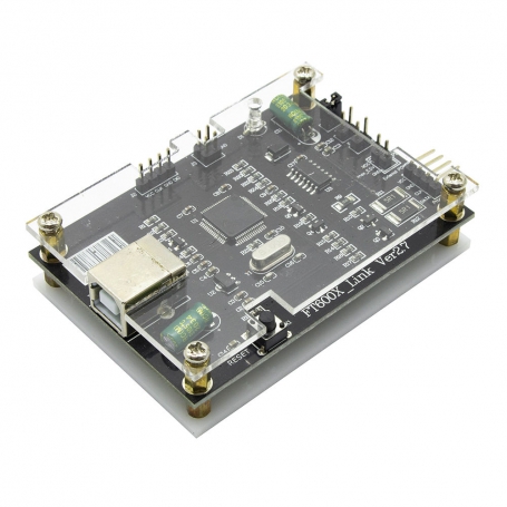
پروگرامر FT600X-Link ورژن 2.7 ابزاری حرفهای برای برنامهنویسی و اشکالزدایی میکروکنترلرهای 8 بیتی سری MS8 ساخت شرکت Fremont Micro Devices است. این دستگاه از طریق رابط USB به رایانه متصل میشود و با استفاده از نرمافزار اختصاصی FMD IDE امکان برنامهنویسی، شبیهسازی و اشکالزدایی تراشهها را فراهم میکند. این پروگرامر از برنامهنویسی آنلاین (In-Circuit) و آفلاین پشتیبانی میکند و دارای چیپ ایزولاسیون داخلی برای افزایش ایمنی و قابلیت اطمینان در ارتباطات است. نرمافزار FMD IDE نسخه 3.1.0 همراه دستگاه ارائه میشود و با پروژههای نسخههای قبلی نیز سازگار است.
مشخصات فنی
رابط ارتباطی: USB 2.0
پشتیبانی از تراشهها: تمامی میکروکنترلرهای 8 بیتی سری MS8
قابلیت برنامهنویسی آنلاین و آفلاین
دارای چیپ ایزولاسیون داخلی برای افزایش ایمنی
سازگار با نرمافزار FMD IDE نسخه 3.1.0
پشتیبانی از سیستمعاملهای Windows XP، Vista، 7، 8، 10
ابعاد فیزیکی: 135x105 میلیمتر
کاربردها
پروگرامر FT600X-Link ورژن 2.7 بهدلیل پشتیبانی گسترده از میکروکنترلرهای سری MS8 و قابلیتهای متنوع، در زمینههای مختلفی کاربرد دارد. از جمله:
برنامهنویسی و اشکالزدایی میکروکنترلرهای 8 بیتی سری MS8
توسعه و تست سیستمهای تعبیهشده و میکروکنترلرها
برنامهنویسی و بهروزرسانی فریمویر دستگاههای الکترونیکی
آموزش و یادگیری در زمینه برنامهنویسی تراشهها و سیستمهای دیجیتال
Introduction
IDE development environment: The upper computer software installation needs to be XP and above.
USB1:The USB port is connected to the PC.
J11: The program target MCU communication control ports, from top to bottom, are:
VCC--> Target IC VCC
GND-> Target IC GND
CLK-> Target IC PAO
DATA--> Target IC PA1
P1: External Power external power input port
J7: Download board GND
J8: Target MCU 3.3V power supply selection
J9: Target MCU 3.7V power supply selection
J10: Target MCU5V power supply selection
J13: external input power
(Note: There are four short-circuit points for J8, J9, J10, and J13, and only one of them can be shorted)
SPWB1: Download board reset button
D1: Indicator light
1. Red LED (always on): Power-on indication, at this time FMDlink did not communicate successfully with the PC.
2. Green LED (always on): FMDlink and PC are connected
3. Yellow LED (always on): FMDlink is in Boot mode, waiting for the firmware to be updated online
4. Yellow LED (flashing): FMDlink is working
Precautions
1. The connection between the PC host and the IDE develprent board is vem simple thatis, the standard USB interface, and there is no need to install additional drivers to use FMDlink
The first time you use it plug in the PC and the system will automatically install the driver and you can use it normally when the driver is installed 2. All power supplies of the FMDlink board are powered by a PC via a USB port of 5V. When the user uses the FMDlink board to debug the target IC, it can be It can be drecty powered by FMDink, and the supply voltage can be adjusted by satching the short-dircat cap. The voltages available for the board are 3.3V, 3.7V and 5V. At the same time the supply voltage can be adjusted by switching The short-cut cap. Only one of the short-circuit caps can be shorted basen them if the user needs an extermal power supply, you need to disconnect the power supply of the target board, and then connect the external power supply to The external power interface of the FMDlink board, and then the power supply is sent to the target board through the VCC of the Program interface, this external Pover The maximum input voltage of the interface cannot exceed 12V 3. Every time you switch the power supply or replace the target IC, you need to press the reset button on the FMDlink board to reconnect the target IC When the LED light on the FMDlink board turns green, it means that the communication with the host computer is successful, and the host computer can only be operated at this time.


